Making a firmware data diode from a £10 network switch
What is a data diode?
A cybersecurity device designed to only allow data flow in one direction.

Sadly, Simon Cowell has no idea what a data diode is, as they are designed for high-security environments such as:
- Defence
- Critical National Infrastructure
- Financial Services
- Energy & Utilities
And are a major component in X domain solutions, not The X Factor...

Get on with it...
Why are they useful?
Data diodes are useful for bridging air-gapped networks where you might not want a network to send traffic back to the other. The green is traffic you want to get out of the network, the red is traffic you don't want to let back in!

They are a key component in cross-domain solutions. The goal of this article is not to explain in detail the use cases of data diodes, but rather to explore the title.
Types of data diode
The behaviour of a data diode can be achieved in a variety of ways.
Hardware defined
The purest form of data diode. A piece of physical hardware that enforces uni-directional data flow, it is physically impossible for data to travel in the reverse direction.
Software defined
Software that provides uni-directional network behaviour. There is no physical hardware enforcing this behaviour, so in theory if the software is vulnerable so is the uni-directional behaviour.
Firmware defined
Uni-directional network behaviour enforced through firmware running directly on hardware; again, there is no physical hardware enforcing uni-directional behaviour. In theory, this is more secure than a software defined data diode as you often require physical access to the hardware to modify the firmware. There is also typically a reduced attack surface against firmware as it has fewer responsibilities and therefore fewer exploitable interfaces than software running on general purpose hardware.
Why aren't they used elsewhere?
Great question, and the answer should be there is no reason.
In practise there are a few barriers to entry that prevent widespread adoption of this technology:
- They are more expensive than software-based solutions, such as firewalls
- They are more complicated to integrate into certain networks
How much do they typically cost?
A quick Google search suggests the average cost of a data diode ranges from "a few thousand to tens of thousands of dollars, depending on several factors".
This cost is a high barrier to entry for most users and often doesn't justify the additional security offered over a traditional firewall.
Why are they expensive?
Hardware defined data diodes are expensive because they require custom hardware. They are the only option providing hardware guarantees on uni-directional behaviour, and are therefore favoured for high-security environments where the highest security is financial justifiable.
Can they be made cheaper?
Yes - well maybe.
Hardware defined diodes will always be the preferred choice in high-security environments, because they provide the strongest guarantees. They will likely continue to command a high price due to custom hardware, supporting the teams of experts required to design and manufacture them as well as R&D costs.
Software defined diodes are free in theory, with a solid understanding of computer networking and some coding skills (or prompting skills) you could whip up something that acts like a data diode. There are a few benefits to this approach, notably the flexibility in features and deployment. The downside being your uni-directional behaviour is only as secure as your software, which is often not very!
Firmware defined diodes, in my opinion, offer a middle ground between hardware guarantees, cost and flexibility. They do not offer hardware uni-directional guarantees; however, they do offer a significantly reduced attack surface versus software defined diodes. As this article will explore, they can also be made from cheap commodity hardware.
So, what how can we make a firmware defined data diode for £10?
The approach
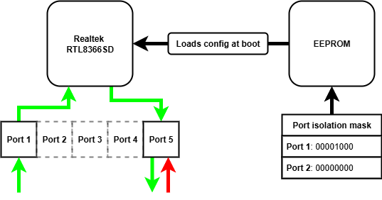
There are many affordable unmanaged network switches on the market, retailing for as low as £5. These devices often contain mature and flexible switch controller chips, which have a number of configuration options for different applications. As these switches are unmanaged, these configuration options cannot be accessed remotely via a management interface - they are "plug and play". The configuration options are read from an EEPROM chip when the device is powered on, and never again after. If we want to modify the configuration options on these unmanaged switches, we need to modify the contents of the EEPROM chip read when power is applied.
What settings could we modify to achieve uni-directional transfer?
There is a number of configuration options that we could use to provide uni-directional behaviour:
| Configuration option | Does what? | So what? |
|---|---|---|
| VLAN | Enables 802.1Q port-based VLAN tagging | We could prevent traffic tagged with a VID from one port reaching another in a different VLAN |
| Port mirroring | Mirrors the received packets from the one port to another | We could copy each packet arriving at the ingress port to the egress port |
| Port isolation | Provides a port isolation mask for a given port | We could allow traffic from the ingress port to reach the egress, and drop all traffic reaching the egress port |
Using the VLAN alone, we cannot achieve the behaviour required - the ingress port is on a different VLAN from the egress port, so ingress traffic cannot reach the egress port. We can achieve uni-directionality by combining the VLAN and port mirroring approach, traffic arrives at the ingress port and is tagged with the ingress PVID. The traffic cannot reach any other port because they are all on different VLANs. With port mirroring enabled, these packets are mirrored to the egress port and on to their destination. Any reverse traffic again is tagged by the egress PVID, but still cannot reach any other port so is dropped. There is no mirroring from egress to ingress port.
Port isolation can be used in isolation of VLAN and port mirroring configuration to achieve uni-directionality. We simply configure the port isolation mask for the ingress port to include the egress port, allowing traffic to reach the egress port. We then configure the egress port isolation mask to nothing, meaning any traffic arriving at the egress port cannot reach any other port.
We can combine all of these configuration options to minimise the risk one option has a vulnerability. All together:
| Configuration | Reason |
|---|---|
| Enable port-based VLAN tagging | Traffic is tagged with the PVID it arrives at, preventing traffic reaching another port |
| Enable dropping VLAN tagged packets | We don't want people to send us traffic they have tagged with a VID |
| Enable mirroring RX traffic | We want to copy received traffic to the egress port |
| Disable mirroring TX traffic | We don't want to copy transmitted traffic to the egress port |
| Disable mirroring RX pause frames | We don't want to copy these frames to the egress port |
| Enable port isolation for all other ports on the ingress port | We want all traffic to be dropped at the ingress port, as the RX traffic will be mirrored to the egress |
| Enable port isolation for all other ports on the egress port | We want all traffic to be dropped at the egress port |
The hardware
I used a TP-Link LS1005G, which I bought from Amazon for £10.

Opening up this switch we can see the various chips.
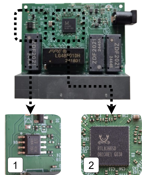
- 1 is the EEPROM chip that contains the configuration options for the switch
- 2 is the switch chip itself, this manages packet switching and will be enforcing our uni-directional behaviour
Flashing the EEPROM
As we explored in the approach we need to modify the configuration settings stored in the EEPROM chip in order to modify the switch behaviour. We can see how the data is loaded from EEPROM when the switch chip is powered up by perusing the datasheet.
The EEPROM interface of the RTL8366 and RTL8369 uses the serial bus EEPROM Serial Management Interface (SMI). The 2K-bit 24C02 EEPROM is read via the EEPROM SMI protocol. When the RTL8366/RTL8369 is powered up, the RTL8366/RTL8369 drives SCK and SDA to read the registers from the EEPROM.
The EEPROM chip is the same type commonly found on PC motherboards for holding the BIOS, which is convenient for us as there is lots of compatible clips for the purpose of flashing these chips. I used a CH341A programmer which came bundled with the correct clip for the EEPROM chip on the switch.
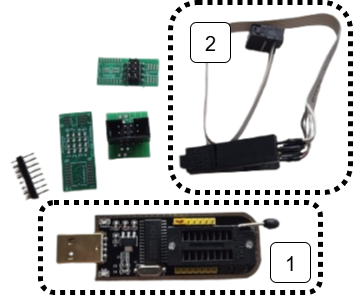
- 1 is the CH341A USB EEPROM programmer
- 2 is the clip attachment for the EEPROM chip
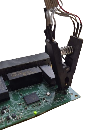
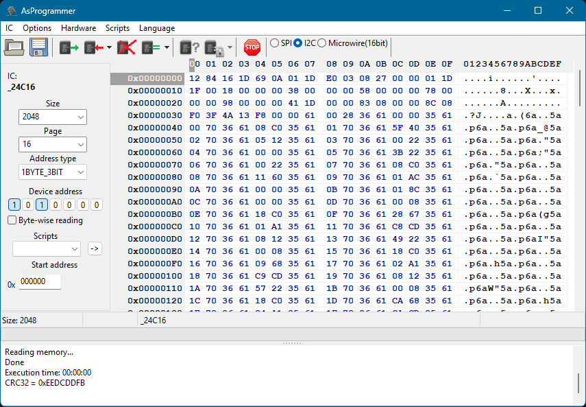
With the clip attached we can now read and program the EEPROM chip using tools such as AsProgrammer. These tools allow us to view the contents of the EEPROM as a hex dump. This isn't particularly useful unless we know how it is interpreted by the switch chip.
What is in the EEPROM?
Looking in the RTL8366 datasheet we can see how the contents of the EEPROM is interpreted by the switch chip.
- 1 the first two bytes are read, these determine when the switch chip will stop reading from EEPROM
- 2 everything else is 2 byte pairs of register location and register value
To set new behaviour on the switch chip we therefore need to modify the first two bytes to read further in EEPROM, then we can put our additional register settings in these newly read bytes.
Great! Now we just need to know which registers to set and what the values need to be.
What registers do we need to set?
To find the registers we need to set we can peruse the Realtek unmanaged switch library. This contains some very helpful resources when finding registers including:
- API documentation - details about the library's functions
- Programming guide - explains the design of the library and offers guidance on how to use it
And if you're feeling lucky, you might just search for the relevant register needed in the registers header file!
Once we've found the required register for the feature we're interested in, we need to know what to put there.
What do we need to put in the registers?
In the API documentation we find:
The forwarding port mask is configured per port. Every packet switched by switch can’t be forwarded to the ports which are not in the forwarding port mask.
CPU force TX (TX portmask in CPU tag) function doesn’t be affected by Port Isolation. Packets which coming from CPU port and have “TX portmask” in CPU tag can be forwarding to any other ports.
Besides this, Port Isolation is the highest priority in forwarding decision.
So we need to set a port isolation mask for two ports that we want to act as our date diode, let's use port 1 and port 5.
We can repeat the above steps to configure other settings on the switch chip, such as port-based VLAN tagging and port mirroring.
Once we know what registers we need to configure, the value we need in each register and therefore how many extra bytes into EEPROM we need to read we have everything to flash the chip with our new behaviour!
How can we check it worked?
Using it as intended of course! Let's send some UDP traffic through it, importantly we shouldn't be able to send TCP because it is bidirectional.
I will be testing the behaviour on Linux, which will require the following tools:
| Tool | For what? |
|---|---|
| netcat | reading and writing UDP |
| wireshark | analysing the packets being sent and received |
| ip | manually configuring ARP entries |
The first two tools appear obvious, but you might be asking what is an ARP entry and how does it need to be manually configured...
What is an ARP table and why do we need to manually configure entries?
The Address Resolution Protocol (ARP) pretty much does what it says on the tin, it resolves IP addresses to a MAC address within a network.
An ARP table is a cache that stores recent IP addresses mapped to MAC addresses. Each of these mappings is known as an ARP entry, for example an ARP entry might look like 192.168.1.10 → 00:1A:2B:3C:4D:5E.
Normally, ARP tables are populated automatically; however, this relies on a bidirectional exchange (sender broadcasts an ARP request, receiver replies with a MAC) - you might be seeing the problem already!
With a data diode in the way there is no way for the receiver to reply with its MAC address, meaning no automatically populated ARP entry!

We need to help out and manually give the ARP table entry relating to the device on the other end of the diode we want to send to. We can use the ip command on Linux to do exactly this!
sudo ip neighbour add <RECEIVING_IP> lladdr <RECEIVING_MAC> dev <NETWORK_ADAPTOR> nud permanent
Finally, we need to set static IPs on both network adaptors. The tool you use to do this is distro dependent.
The setup with static IPs looks as follows:
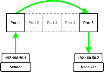
Once we have manually configured the ARP entry for the receiving device on the other end of the diode we can start sending and receiving UDP packets.
To start we need to start netcat listening on the receiving device, I'm using port 5005 for reasons.
nc --listen --udp 5005
Then we can start wireshark to capture packets arriving at the network adapter on the receiving device.
Now on the sending device we can start wireshark capturing packets being sent from the sending device.
Finally, we can send packets from the sending device using netcat!
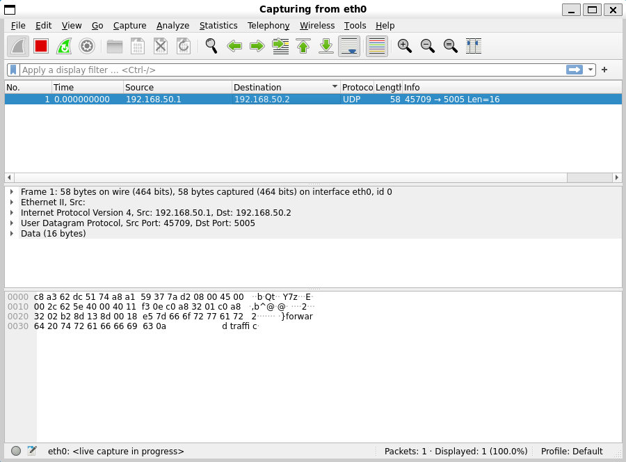
echo "forward traffic" | nc --udp 192.168.50.2 5005
On the sending machine we see packets go out...
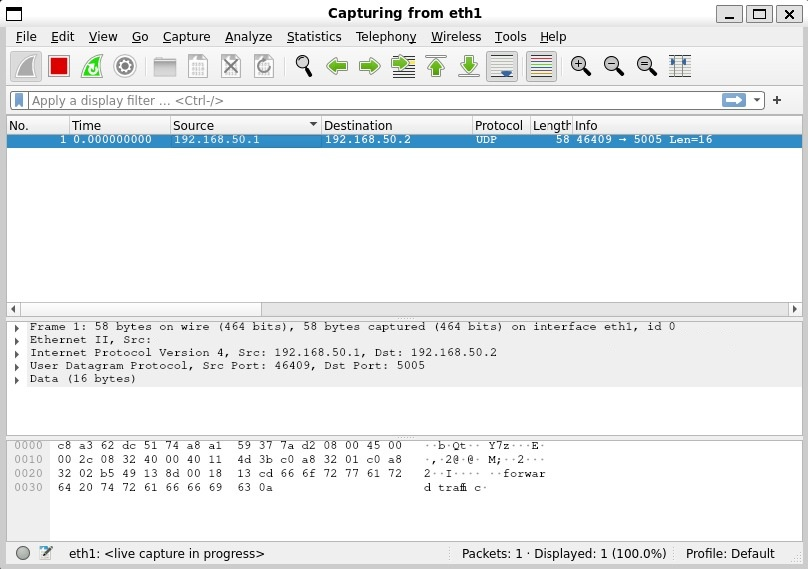
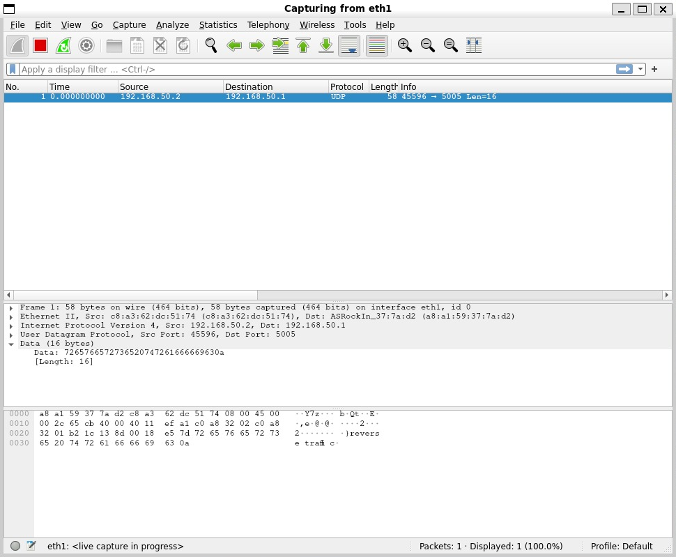
On the receiving machine we see packets arrive!
Let's try the same test with TCP packets and see what happens...
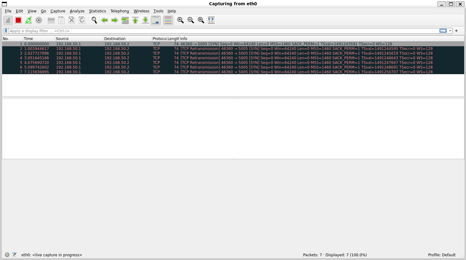
We see a SYN packet go out, this is the initial handshake packet of the TCP protocol, but sadly his friends behind the data diode can't ACK back... in a desperate attempt to reach his unresponsive friends he tries to re-transmit the SYN packet many times to no avail, it's all a bit sad.
Maybe they can send something back over UDP, lets send some packets from the receiver...
echo "reverse traffic" | nc --udp 192.168.50.1 5005
On the receiver machine we can see packets go out...
And on the sender machine we see...
Nothing!
Conclusion
What I hope this article has demonstrated is that a modified unmanaged network switch can operate as a firmware defined data diode with a little bit of a tweaking.
Future work
There is a number of possibilities this initial work opens up, such as:
- Experimenting with other features on the switch chips
- Experimenting with more complex architectures to build towards cross domain solutions
- Experimenting with the 8 port variants
Acknowledgements
Thanks to Rene and the Open source data diode repository, where the original idea came from. I will be contributing the guide and registers for setting up a device for yourself!